A seismic load is the force a building has to resist during an earthquake. The ground moves. The building's mass wants to keep still. That tug creates the force inside the structure — different from wind, which pushes on the outside.
What Seismic Loads Actually Do
Wind pushes on the walls and roof. Earthquake shaking moves the ground, and the building's mass resists that movement. That resistance is where the internal force comes from.
Heavier buildings feel more force. Irregular buildings twist. Soft soils amplify the shaking. Weak connections give way before the members they connect. All of those are the reasons seismic design is different from every other kind of load.

The Four Questions Behind Every Seismic Design
Strip out the equations for a moment. Every seismic problem is really four questions in order.
How strong is the shaking at this site? That depends on location, soil, and which hazard map the local code adopts. Two identical buildings a few miles apart can have very different design forces because one sits on rock and one on soft soil.
How heavy is the building? Every pound of permanent mass creates inertial force during shaking. This is why steel-frame lightweight buildings often have smaller seismic demands than heavy concrete structures on the same site.
How does the building resist side movement? Shear walls, braced frames, moment frames, dual systems, base isolation. Each choice locks in a level of ductility, a detailing standard, and code requirements the designer cannot skip later.
Can the force travel safely to the ground? The load path from roof to soil is the whole point. A calculation without a continuous path is a paper exercise.
Strength alone is not the answer. A seismic system needs ductility — the ability to bend, crack in controlled places, and absorb energy without sudden collapse.
What Students Should Learn First
Do not start with software. Software will hide the problem faster than it solves it. Start with the load path. If you cannot explain out loud how force moves from the roof down to the soil, no ETABS model will save you in a jury.

The core terms are worth memorizing before anything else. Mass is the weight that creates inertial force. Base shear is the total horizontal force at the base. Drift is how far one floor moves sideways relative to the one below. Torsion is twisting from uneven stiffness or mass. Ductility is controlled deformation instead of brittle failure. The load path is the physical route force takes from diaphragms through vertical elements to foundations to soil.
What Professionals Have to Check
A real seismic design is more than a base shear number. It has to include the correct code edition, local adoption, site class, risk category, structural system, detailing rules, drift limits, nonstructural anchorage, foundation behavior, and coordination during construction. Seismic design fails most often when one of these gets treated as a small detail.
Current Code References
The U.S. loading standard is ASCE/SEI 7-22. The 2024 International Building Code references ASCE 7-22 for most seismic requirements, though some cities and states still enforce older editions. Always check the authority having jurisdiction before design starts.
In Canada, seismic values come from the National Building Code of Canada. The current federal model code is NBC 2025, though many active projects were permitted under NBC 2020 or a provincial version.
In Europe, Eurocode 8 is the framework, but national annexes can produce meaningfully different design values in different countries.
For existing buildings, ASCE/SEI 41-23 and FEMA guidance for weak-story wood-frame buildings apply where relevant. Retrofit work uses a different mindset than new construction.
Basic Seismic Formula
The simplified form of base shear is:
V = Cs × W
Where V is the seismic base shear, Cs is the seismic response coefficient, and W is the effective seismic weight.
This is useful for teaching, not for designing anything you would sign. In code work, Cs depends on mapped ground motion, site class, risk category, importance factor, structural system, response modification factor R, fundamental period T, and both a code minimum and a code maximum. The full formula in ASCE 7-22 §12.8 is:
Cs = SDS × Ie / R
With upper limits from Equations 12.8-3 and 12.8-4, and lower limits from 12.8-5 and 12.8-6. Miss one of those bounds and the base shear you report is not what the code requires.
Simple Seismic Load Example
This is a teaching example only, not a permit-ready design.
Assume a four-story office building with a total seismic weight of 1,200,000 lb, equal 300,000 lb per floor, story heights of 10, 20, 30, and 40 feet above grade, and a simplified seismic coefficient of 0.20.
Base shear:
V = 0.20 × 1,200,000 = 240,000 lb
The lateral system must be checked for about 240,000 lb of horizontal seismic force in this simplified case.
How the Force Distributes Up the Building
Seismic force does not spread evenly by floor. Upper floors typically attract more lateral force because they create a larger overturning effect. Under ASCE 7-22 Equation 12.8-11, the force at each level is:
Fx = Cvx × V
Where Cvx = (wx × hx^k) / Σ(wi × hi^k), and the exponent k depends on the building's fundamental period T. For T ≤ 0.5 s, k = 1. For T ≥ 2.5 s, k = 2. Linear interpolation in between.
A simplified vertical distribution for the example above might look like this:
| Floor | Approximate Lateral Force | What It Means |
|---|---|---|
| 4 | 128,000 lb | Top level attracts the largest share in this simplified case. |
| 3 | 72,000 lb | Middle-upper level still carries major lateral demand. |
| 2 | 32,000 lb | Lower level carries less floor force but must transfer force downward. |
| 1 | 8,000 lb | Ground level collects and transfers all force into the foundation. |
| Total | 240,000 lb | Total base shear. |
The lesson is that the ground floor may not have the largest floor force, but it has to carry the accumulated force from every floor above. Weak ground floors, open parking levels, poor anchorage, and missing shear walls are serious seismic problems for this reason.

Where Students and Junior Engineers Get Seismic Problems Wrong
Most seismic tutorials teach the correct method and stop. That leaves out the more useful information: which mistakes are made over and over on coursework, licensing exams, and early-career reviews. The following list is compiled from senior engineer reviews (notably Terry Heausler's work in Structure Magazine) and from patterns that show up repeatedly in exam feedback and design review comments.
Miscalculating the Effective Seismic Weight W
W is not simply the dead load. Under ASCE 7-22 §12.7.2, it also includes 25% of the floor live load in storage areas, at least 10 psf for partitions where partition loads are part of the design, permanent equipment operating weight, and 20% of flat-roof snow load when the ground snow load exceeds 30 psf. The most common student error is including all floor live load, which is wrong — occupants sway with the building and don't contribute meaningfully to inertial force. The second most common error is forgetting rooftop mechanical equipment. Get W wrong by 15% and every downstream number is wrong by 15%.
Using an R Factor Without Meeting Its Detailing Requirements
R is not a menu item. Every R value in Table 12.2-1 comes with detailing rules from the material standards — ACI 318 Chapter 18 for concrete, AISC 341 for steel — and system limits based on Seismic Design Category. Picking R = 8 for a special steel moment frame drops the design force dramatically, but only if the frame is actually detailed as a special moment frame with prequalified connections, protected zones, and continuity plates. Students routinely use R = 8 in coursework problems without checking whether the system chosen is permitted in that SDC per Table 12.2-1 at all. That gets flagged on exams and by real reviewers.
Confusing R, Cd, and Ω₀
These three factors are related but do different jobs. R reduces the design force to account for expected inelastic behavior. Cd amplifies elastic drift back to expected real drift for serviceability checks. Ω₀ is the overstrength factor used for brittle elements — collectors, anchor bolts, foundation connections — that cannot yield. Students mix these constantly. A common exam error is applying R to size the collector when Ω₀ is required, which under-designs the very element the code is trying to protect.
Getting the Fundamental Period T Wrong
T can be estimated from the ASCE 7-22 §12.8.2.1 approximate formula (Ta = Ct × h^x) or computed from a modal analysis. The approximate formula is intentionally conservative — it usually gives a shorter period than reality, which means a higher Cs, which means a higher design force. Students often use a computed period from software without applying the code cap (typically Cu × Ta), which then artificially lowers the design force below what the code allows. On the flip side, using Ta = 0.1N as a rule of thumb on an exam problem is fine for a first check but not for a final answer.
Guessing the Site Class
Site class comes from a geotechnical investigation, not a guess. When no data is provided, ASCE 7-22 §11.4.3 requires assuming Site Class D unless a stiffer class can be justified. Students often default to Site Class C on the assumption that "medium is safe" — that is neither the code default nor conservative. Site class changes Fa and Fv, which changes SDS and SD1, which changes everything downstream.
Skipping the Cs Bounds
Equation 12.8-2 gives an initial Cs value, but ASCE 7-22 requires Cs to be capped by Equations 12.8-3 and 12.8-4 (period-dependent maximums) and to be no less than 12.8-5 and, for certain high-seismic sites, 12.8-6. A common student error is calculating Cs from 12.8-2 and stopping. The bounds exist because the base equation can produce unrealistically high or low values at extreme periods.
Ignoring Torsional Amplification and Redundancy
Real buildings are not perfectly regular. ASCE 7-22 requires accidental torsion (5% offset of the center of mass) for every diaphragm, with amplification (Ax) when a torsional irregularity exists. The redundancy factor ρ can also increase the design force to 1.3 × the calculated value when the lateral system lacks enough redundancy. Students frequently forget both, and both are common review comments on early-career designs.
Mixing ASD and LRFD Load Combinations
Seismic forces from ASCE 7 come out at strength design level. Using them in an ASD combination requires the 0.7 factor from §2.4. Using them without adjustment in an ASD combination — a common mistake in wood-frame exam problems — overdesigns the structure by roughly 40%. The reverse mistake, applying 0.7 twice or forgetting it entirely in LRFD, is equally common.
Forgetting the Nonstructural Components
ASCE 7-22 Chapter 13 covers nonstructural components — ceilings, ducts, equipment, cladding, piping — and their seismic anchorage. This chapter is skipped in most textbooks and most coursework. It is the source of the majority of losses in real earthquakes because dropped ceilings, unbraced equipment, and toppled shelves injure people even when the structure survives intact. On the PE and SE exams, Chapter 13 problems show up regularly and catch out students who only studied Chapter 12.
Seismic Loads vs Wind Loads
Wind and seismic both create lateral demand. They are not the same problem.
| Issue | Wind Load | Seismic Load |
|---|---|---|
| Source | Air pressure on the outside of the building | Ground motion acting through the building's mass |
| Main concern | Stiffness, cladding, drift, occupant comfort | Ductility, energy dissipation, collapse prevention |
| Direction | Usually one main direction at a time | Reverses quickly and can act in multiple directions |
| Failure pattern | Envelope damage, drift damage, connection distress | Soft-story collapse, torsion, brittle joints, anchorage failure |
| Load combinations | Different set in ASCE 7 §2 | Different set, uses Em with Ω₀ for brittle elements |
Designing a building as if lateral force is lateral force gets buildings killed. Seismic detailing has to survive repeated movement, load reversals, and real energy demand, which is fundamentally different from resisting a steady wind push.

Static, Response Spectrum, and Time-History Analysis
Different projects need different analysis methods. Height, regularity, risk category, and complexity all decide which method is allowed and which is required.
| Method | Best Use | Limit |
|---|---|---|
| Equivalent lateral force | Simple, regular, lower-risk buildings where allowed by code | Too simple for irregular or taller structures |
| Response spectrum analysis | Buildings where modal behavior matters | Does not capture full time-by-time nonlinear behavior |
| Time-history analysis | Irregular, tall, critical, or performance-based projects | Requires careful ground-motion selection and expert review |
Common Lateral Systems
The lateral system is what resists earthquake movement. It has to be continuous, balanced, and detailed for ductility.
Shear walls are stiff vertical walls that resist racking and transfer force to the foundation. Concrete and masonry shear walls are common for high-force buildings; wood shear walls with plywood or OSB sheathing are the standard for light-frame houses.
Braced frames use diagonal members to resist lateral movement through tension and compression. Concentric and eccentric braced frames each have distinct code detailing.
Moment frames are beam-column frames designed to bend and dissipate energy ductilely at prequalified connections.
Dual systems combine frames with walls or braces where more redundancy is required. The frame typically has to carry at least 25% of the total lateral force independently.
Base isolation uses special bearings or devices to reduce force transfer into the structure. Common on hospitals, data centers, and other critical facilities.
Where Buildings Fail in Earthquakes
Earthquakes expose weak links. A building does not need to fail everywhere. One bad level, one missing connection, or one brittle detail can control the whole collapse pattern.

Soft-Story Failure
A soft story is one level that is much weaker or more flexible than the levels above it. Open parking floors, storefronts, and tall ground-floor openings are the classic examples. This is what killed apartment buildings in the 1994 Northridge earthquake.
Torsional Failure
Torsion happens when the building twists instead of moving evenly. Uneven wall placement, irregular floor plans, and heavy mass on one side all cause it. A corner unit in an irregular building sees the worst of it.
Unreinforced Masonry Failure
Brick or block walls without reinforcement crack and separate during shaking. Older masonry buildings usually need wall-to-diaphragm anchorage, parapet bracing, and floor tie-in retrofits.
Short Column Failure
A short column is stiffer than expected because a partial-height wall, stair, ramp, or infill panel restrains it. Stiffer columns attract more force. The result is often sudden diagonal shear cracking with no ductile warning.
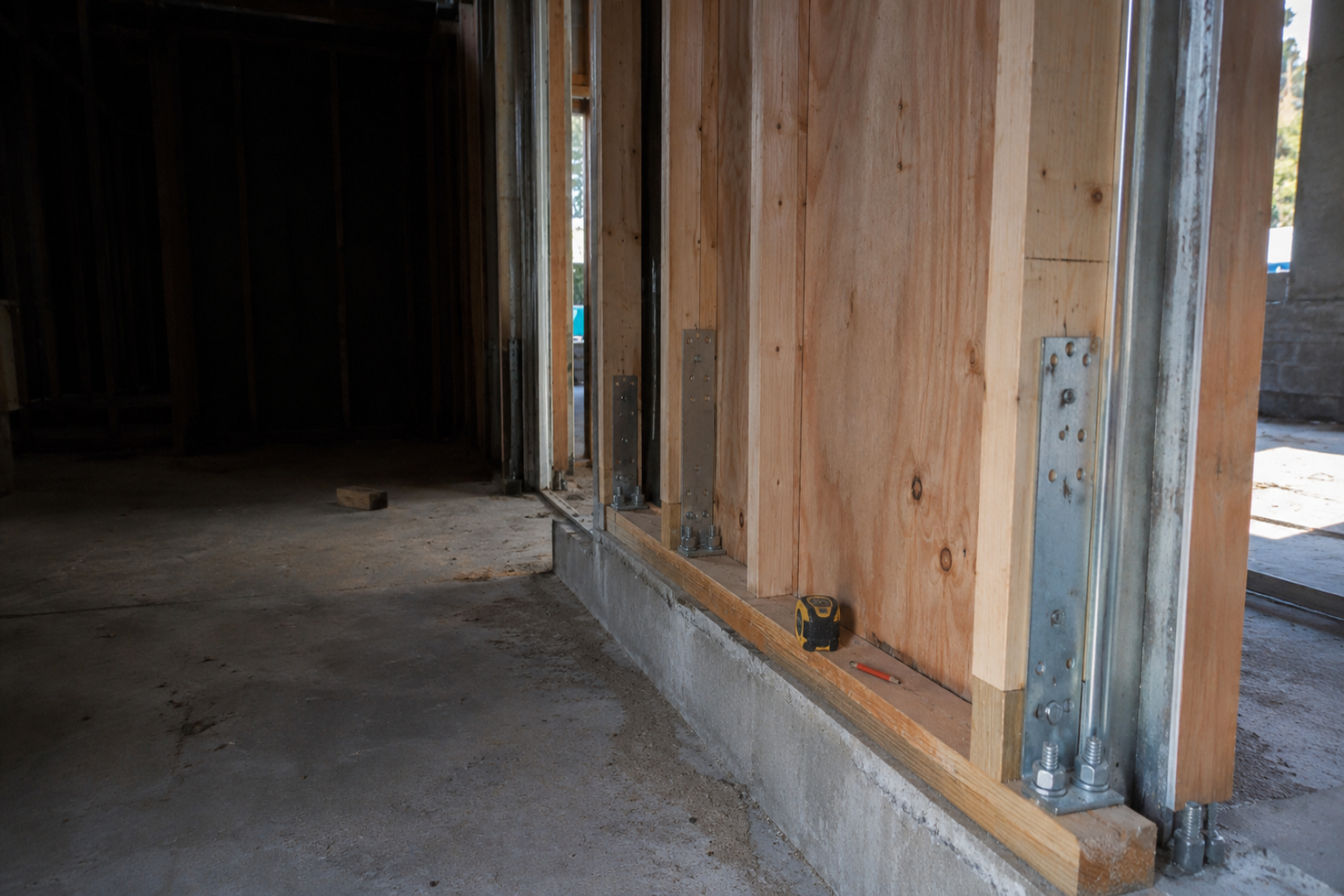
Poor Detailing
Bad rebar hooks, weak lap splices, missing confinement steel, poor welds, thin gusset plates, weak anchor bolts, and missing hold-downs create local failures that then spread through the structure. ACI 318 §18.6.4 requires 135° hooks with 6db extensions for confinement reinforcement in special systems in SDC D–F. A 90° hook is a common error that voids the seismic system entirely.
The Load Path Is the Real Story
A clean seismic load path runs from the diaphragms down through the vertical elements to the foundations and soil:
Roof and floor diaphragms → collectors and chords → shear walls, braces, or frames → foundations → soil
Every arrow needs a real physical connection. If the diaphragm is not tied to the wall, if the wall is not tied to the foundation, or if the foundation is not designed for sliding and overturning, the system is incomplete no matter how good the base shear number looks.
For related foundation work, see building foundations, foundation excavation depth, and foundation building materials.
Foundations and Soil Matter
Seismic design does not stop at the bottom of the wall. Soil can amplify shaking, settle, spread laterally, liquefy, or reduce support during an earthquake.
Foundation checks typically include sliding resistance, overturning resistance, uplift at hold-downs and wall ends, tie beams or grade beams between supports, mat behavior on soft soil, deep foundation response for piles or caissons, and soil-structure interaction where required. For Site Class F or liquefiable sites, a site-specific ground response analysis is required by ASCE 7-22 §11.4.8.
Existing Buildings and Seismic Retrofit
Existing buildings need a different mindset from new construction. The point is not to pretend the old building is new. It is to identify deficiencies, choose a performance target, and improve the weak parts without creating new failure points.
Common retrofit scope includes anchoring walls to roof and floor diaphragms, adding plywood shear walls in wood buildings, adding steel moment frames at soft ground floors, bracing parapets and chimneys, strengthening foundations and sill connections, adding collectors and hold-downs, and addressing nonstructural hazards.
A retrofit that just adds strength at random can make things worse — attracting more force to elements that cannot carry it. The point is a more reliable load path, not a stronger point in isolation.
Retaining Walls, Bridges, and Nonbuilding Structures
Seismic loads also affect retaining walls, bridges, tanks, towers, and other nonbuilding structures. Retaining walls need dynamic earth pressure checks (typically Mononobe-Okabe), sliding and overturning verification, drainage, and backfill behavior review. Bridges require displacement capacity, bearing checks, seat length, pier ductility, foundation movement, and sometimes isolation or restrainers.
A building method copied directly onto a bridge or a tall retaining wall usually misses the failure modes that matter for those structures.
Schools, Hospitals, and Critical Buildings
Critical buildings have a higher bar than collapse prevention. Many have to remain usable after the earthquake. Hospitals, fire stations, emergency operations centers, and essential schools carry higher risk categories, stricter detailing, and demanding nonstructural requirements. For these buildings, "the frame is strong" is not enough. Mechanical equipment, ceilings, generators, tanks, medical gas lines, and emergency power all need seismic restraint that has been coordinated with the structural design.
Software Used for Seismic Design
Software helps. It does not replace judgment. A model is only as reliable as the assumptions inside it.
| Tool | Common Use | Watch Out For |
|---|---|---|
| ETABS | Multi-story building analysis and design | Model assumptions, diaphragm behavior, mass source, load combinations |
| SAP2000 | General structures, bridges, frames, dynamic analysis | Boundary conditions, modal behavior, connection assumptions |
| STAAD | Steel, concrete, industrial, and some bridge work | Code setup, member releases, seismic parameters |
| OpenSees | Advanced nonlinear and research-level modeling | Requires specialist knowledge and careful validation |
| RFEM / RSTAB | Structural modeling with Eurocode workflows | Regional code settings and interpretation |
Seismic Design Checklist

- Confirm the local code edition and any adopted amendments.
- Confirm site seismic hazard values from the correct official tool or code map.
- Confirm site class from geotechnical information where required, and use Site Class D as default only where allowed.
- Set the correct risk category and importance factor.
- Identify the seismic force-resisting system and confirm it is permitted in the SDC per Table 12.2-1.
- Check that the lateral system is continuous from roof to foundation.
- Check torsional and vertical irregularities, including accidental torsion.
- Check story drift, drift amplification with Cd, and P-delta effects.
- Check diaphragm behavior, collectors, chords, drag struts, and connections — sizing brittle elements with Ω₀.
- Check foundation sliding, overturning, uplift, and soil support.
- Brace heavy nonstructural components per Chapter 13.
- Coordinate drawings so the seismic details can actually be built in the field.
Common Design Mistakes to Avoid
- Using the wrong code edition. The adopted local code controls the project, not the newest book on your desk.
- Guessing the site class. Soil can change the design force significantly.
- Treating seismic like wind. Seismic detailing requires ductility and load-reversal capacity.
- Ignoring torsion. Asymmetrical buildings twist during shaking whether the designer accounts for it or not.
- Forgetting rooftop equipment. Effective seismic weight has to include permanent loads that ride with the structure.
- Stopping shear walls or braces too early. Discontinuous systems create weak transfer levels that concentrate damage.
- Skipping nonstructural restraint. Ceilings, tanks, ducts, shelves, and pipes injure people even when the frame survives.
FAQ
Are seismic loads horizontal or vertical?
Both can matter. Horizontal seismic force is the main design focus, but vertical seismic effects are important for cantilevers, long-span elements, near-fault sites, bridges, equipment anchors, and other sensitive conditions. ASCE 7-22 requires vertical seismic effects for structures in SDC C through F.
Is base shear the same as earthquake force?
No. Base shear is a design force representing the total lateral seismic demand at the base of the structure under code procedures. It is not the full physical earthquake event, and it is not what an accelerograph records.
Do architects need to calculate seismic loads?
Architects generally do not perform final structural calculations unless they are licensed and qualified to do so. But architects should understand seismic layout, load path, soft stories, heavy cladding, irregular plans, and where the structural system needs room to work.
Do students need software first?
No. Learn the load path first. Software can hide mistakes if you don't understand mass, stiffness, drift, torsion, and foundations before you touch it.
What is the most common seismic design mistake?
A broken load path. Forces get calculated, but the physical connections between diaphragm, wall, foundation, and soil cannot actually carry those forces. The math looks right and the building would still fail.
Can an old building be made earthquake-safe?
Many older buildings can be improved. The correct scope depends on building type, hazard level, condition, budget, and performance target. A good retrofit targets the known weak points rather than adding random strength.
What to Check Next
If you are studying seismic loads, start with the basic force path and base shear logic. If you are working on a real project, confirm the adopted code, site class, risk category, structural system, drift limits, foundation assumptions, and nonstructural restraint before relying on any calculation.
Seismic design is not about making a building rigid. It is about giving the building a clear, ductile, connected way to move without collapsing.